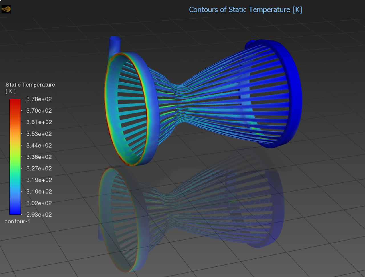
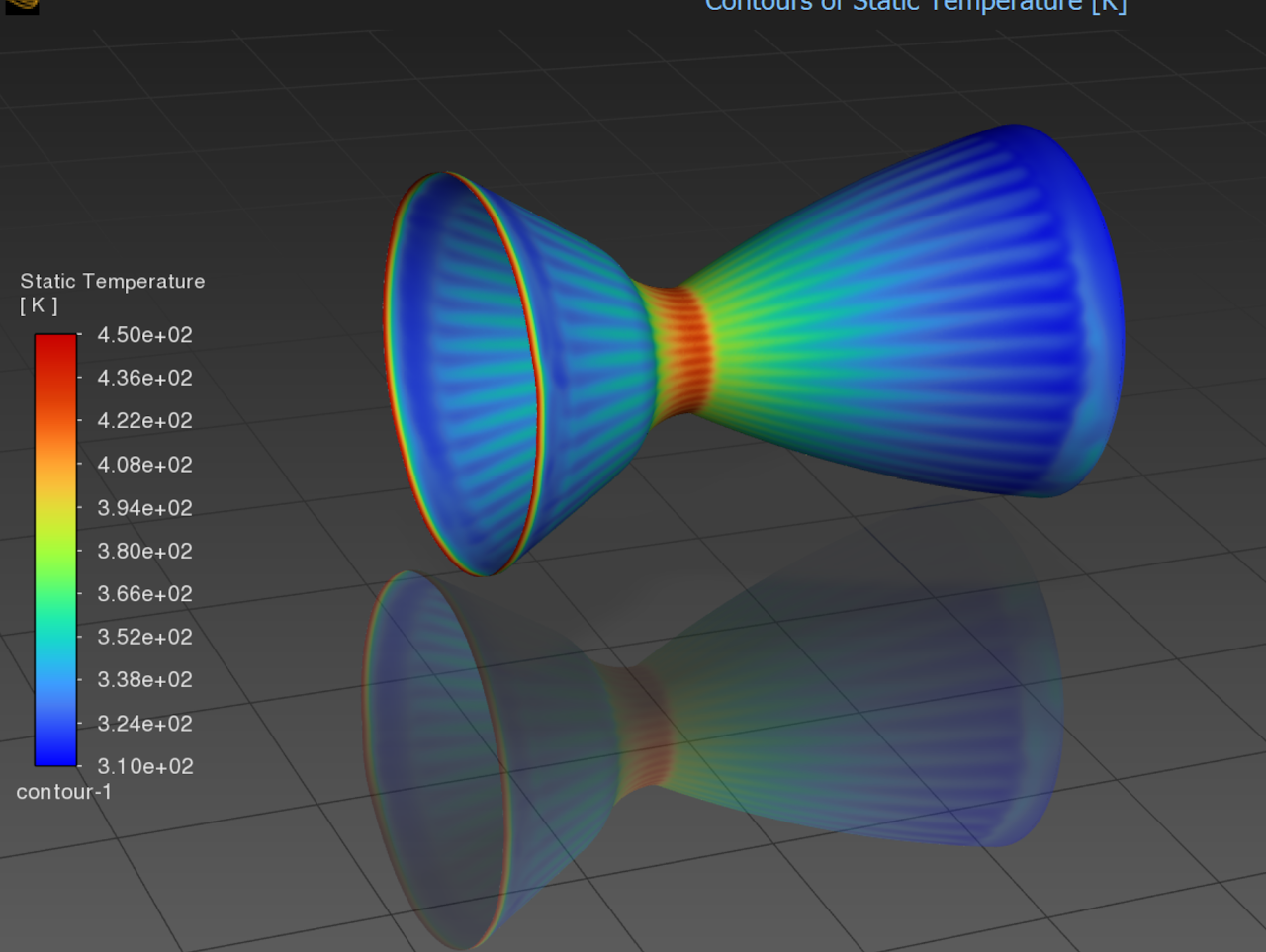
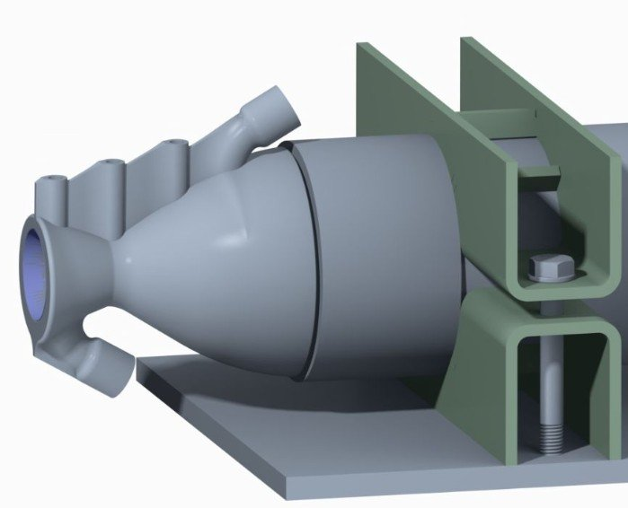
This is the regeneratively cooled nozzle designed for Monash HPR's MkIII engine for Race2Space 2025. My job was the thermal and structural side of the nozzle getting the wall to survive combustion heat flux without melting or cracking.
Design & Manufacturing
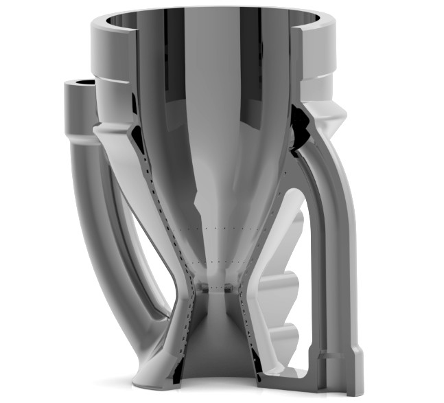
The nozzle is printed in AlSi10Mg, with helical cooling channels wrapped around the wall. The throat carries the tightest channels, since that's where heat flux peaks, and I accepted a higher pressure drop there to buy more cooling. The bell and converging sections run wider, thinner channels instead. Thermal load is lower there, so I could open the channels up and save mass and pressure drop where it didn't cost me anything. At the high heat flux zones I also added 0.8 mm film cooling ports, providing a thin layer of coolant straight into the hot gas boundary layer as a backup on top of the channel cooling.
RPA's performance outputs drive the geometry directly. Throat radius, converging length, and wall thickness all update automatically if the engine's operating point moves. I checked every wall to a factor of safety of 2 against the CFD temperature limits, then fed those thermal results into structural FEA so pressure and thermal loading were captured together rather than treated separately. I also designed around the AM constraints, minimum channel diameter, overhang limits, and clear paths for powder removal.
Simulation
I ran a conjugate heat transfer analysis on the MkIII nozzle in ANSYS Fluent, solving the hot combustion gas and cooling water together through the nozzle wall in one steady-state, single-phase run. Boundary conditions came from the MkIII cooling parameters of 8 kg/s of water at 20 bar through the coolant channels against a 60 bar, 3100 K combustion gas inlet. I initialised with FMG across 5 grid levels and ran it to convergence over 604 iterations, tracking point probes and area and volume-weighted temperature monitors on both sides of the wall.
The throat wall converged at 424 K, with the area-averaged wall temperature sitting around 380 K.